应用 信息
(持续)
在 许多 具体情况 这 preferred 模式 的 运作 是 这 con-
tinuous mode 它 提供 更好 输出 power 更小的 顶峰
switch inductor 和 二极管 currents 和 能 有 更小的 输出-
放 波纹 voltage 但是 它 做 需要 大 inductor 值
至 保持 这 inductor 电流 流 continuously 特别
在 低 输出 加载 电流 andor 高 输入 voltages
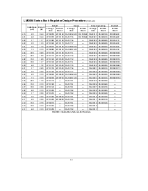
至 使简化 这 inductor 选择 process 一个 inductor se-
lection 手册 (nomograph) 是 设计 (看
计算数量 5
通过
8
) 这个 手册 假设 那 这 调整器 是 operat-
ing 在 这 持续的 mode 和 选择 一个 inductor 那 将
准许 一个 顶峰-至-顶峰 inductor 波纹 电流 至 是 一个 确实
percentage 的 这 最大 设计 加载 current 这个 顶峰-
至-顶峰 inductor 波纹 电流 percentage 是 不 fixed 但是 是
允许 至 改变 作 不同的 设计 加载 电流 是 se-
lected (看
图示 16
)
TLH12583–31
图示 16 (
D
I
IND
) 顶峰-至-顶峰 Inductor 波纹 电流
(作 一个 Percentage 的 这 加载 电流) vs 加载 电流
用 准许 这 percentage 的 inductor 波纹 电流 至 在-
crease 为 低 加载 currents 这 inductor 值 和 大小 能
是 保持 相当地 low
当 运行 在 这 持续的 mode 这 inductor cur-
rent 波形 范围 从 一个 triangular 至 一个 sawtooth 类型
的 波形 (取决于 在 这 输入 电压) 和 这 aver-
age 值 的 这个 电流 波形 equal 至 这 直流 输出
加载 current
Inductors 是 有 在 不同的 样式 此类 作 pot core
toroid e-core bobbin core etc 作 好 作 不同的 核心
materials 此类 作 ferrites 和 powdered iron 这 least ex-
pensive 这 bobbin rod 或者 stick core 组成 的 线
伤害 在 一个 ferrite bobbin 这个 类型 的 构建 制造
为 一个 inexpensive inductor 但是 自从 这 有磁性的 通量 是
不 完全地 包含 在里面 这 core 它 发生 更多
electro-有磁性的 干扰 (eml) 这个 有磁性的 通量 能
induce 电压 在 nearby 打印 电路 traces 因此 caus-
ing 问题 和 两个都 这 切换 调整器 运作
和 nearby 敏感的 circuitry 和 能 给 incorrect scope
readings 因为 的 induced 电压 在 这 scope probe
也 看 部分 在 打开 核心 Inductors
当 多样的 切换 regulators 是 located 在 这 一样
PC board 打开 核心 磁性材料 能 导致 干扰 是-
tween 二 或者 更多 的 这 调整器 circuits 特别 在
高 currents 一个 torroid 或者 e-核心 inductor (关闭 有磁性的
结构) 应当 是 使用 在 这些 situations
这 inductors 列表 在 这 选择 chart 包含 ferrite
e-核心 构建 为 Schott ferrite bobbin 核心 为 Renco
和 Coilcraft 和 powdered iron 环形线圈 为 脉冲波 engineer-
ing
Exceeding 一个 inductor’s 最大 电流 比率 将 导致
这 inductor 至 overheat 因为 的 这 铜 线 losses
或者 这 核心 将 saturate 如果 这 inductor begins 至 saturate
这 电感 减少 迅速 和 这 inductor begins 至
看 mainly resistive (这 直流 阻抗 的 这 winding) 这个
能 导致 这 转变 电流 至 上升 非常 迅速 和 强迫
这 转变 在 一个 循环-用-循环 电流 limit 因此 减少
这 直流 输出 加载 current 这个 能 也 结果 在 overheat-
ing 的 这 inductor andor 这 LM2596 不同的 inductor
类型 有 不同的 饱和 characteristics 和 这个
应当 是 保持 在 mind 当 selecting 一个 inductor
这 inductor manufacturer’s 数据 薄板 包含 电流
和 活力 限制 至 避免 inductor saturation
DISCONTINUOUS 模式 运作
这 选择 手册 chooses inductor 值 合适的 为
持续的 模式 operation 但是 为 低 电流 产品
andor 高 输入 voltages 一个 discontinuous 模式 设计
将 是 一个 更好的 choice 它 将 使用 一个 inductor 那 将
是 physically smaller 和 将 需要 仅有的 一个 half 至 一个
第三 这 电感 值 需要 为 一个 持续的 模式
design 这 顶峰 转变 和 inductor 电流 将 是 高等级的
在 一个 discontinuous design 但是 在 这些 低 加载 电流 (1a
和 在下) 这 最大 转变 电流 将 安静的 是 较少
比 这 转变 电流 limit
Discontinuous 运作 能 有 电压 波形 那
是 considerable 不同的 比 一个 持续的 design 这
输出 管脚 (转变) 波形 能 有 一些 damped sinus-
oidal ringing present (看
图示 1
photo titled discontinu-
ous 模式 切换 波形) 这个 ringing 是 正常的 为
discontinuous operation 和 是 不 造成 用 反馈
循环 instabilities 在 discontinuous operation 那里 是 一个 peri-
od 的 时间 在哪里 neither 这 转变 或者 这 二极管 是 con-
ducting 和 这 inductor 电流 有 dropped 至 zero dur-
ing 这个 time 一个 小 数量 的 活力 能 circulate 是-
tween 这 inductor 和 这 switchdiode parasitic capaci-
tance 造成 这个 典型的 ringing 正常情况下 这个 环绕-
ing 是 不 一个 problem 除非 这 振幅 变为 好
足够的 至 超过 这 输入 voltage 和 甚至 then 那里 是
非常 little 活力 呈现 至 导致 damage
不同的 inductor 类型 andor 核心 材料 生产 dif-
ferent amounts 的 这个 典型的 ringing Ferrite 核心 在-
ductors 有 非常 little 核心 丧失 和 因此 生产 这
大多数 ringing 这 高等级的 核心 丧失 的 powdered iron induc-
tors 生产 较少 ringing 如果 desired 一个 序列 RC 可以 是
放置 在 并行的 和 这 inductor 至 dampen 这 ringing
这 计算机 aided 设计 软件
切换器 制造 sim-
ple
(版本 43) 将 提供 所有 组件 值 为 con-
tinuous 和 discontinuous 模式 的 operation
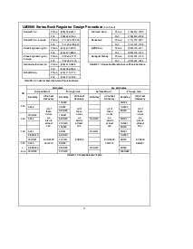
TLH12583–32
图示 17 邮递 波纹 过滤 波形
17